 |
Ford Model-A Notebook (Article #1)
|
![]()

![]()
|
By DJ.Voyce
What I'd like to do now, after much encouragement from a few of my cyber buddies on Dale Clinton's Internet Bulletin Board, is to try and disprove (if you continue reading this of course) all the untruths and rumours and dispel any fears which you may secretly be harbouring concerning the "Dark Science" of pressure plate operation and repair. Remember that someone put the thing together in the first place and as there is definitely no brain surgery involved (otherwise I wouldn't be writing this) you can do the same. I will now try and explain in layman's terms the step by step dismantling, inspection, assembly and adjustment procedure which can easily be carried out in your home workshop, without the aid of mirrors and, providing the laid down procedure is carefully followed, with absolute no risk to your personal well being, or danger to the surrounding environment or ozone layer. I would also suggest that you read this text in its entirety before getting too enthusiastic with your favourite set of wrenches. Before I start to try and play teacher, let me first state that I make no excuse for the quality of the photography, nor the fact that this article may appear to some to be long-winded and seemingly over explained or over simplified, as there are those of us out there who are possessed with only at best, very rudimentary mechanical skills and are further disadvantaged by having come into this world with five thumbs on each hand. The intention therefore is to provide detailed step by step instructions which will enable any reader, no matter what their ability, to safely carry out a full tear down and repair operation on the Model A pressure plate. For the non-technical out there, let's first try to understand fully the function of the clutch, pressure plate and flywheel assembly relating to the drive train, and that is to provide an interruptable mechanical connection (as opposed to a fluid connection in an auto-trans) between the engine and the gearbox. This is primarily to allow selection of any gear whilst the vehicle is stationary or in motion, with the engine running, and to achieve a gentle transition from rest, to either a forward or reverse motion, and then to further allow the selection of other gears once the vehicle is in motion. The way this is achieved is quite simple, and even if you don't fully understand the principal initially, don't despair as I'm sure it'll become clearer as we go along.
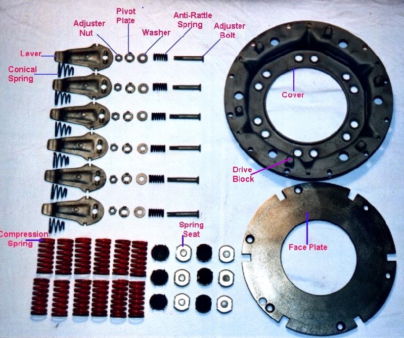
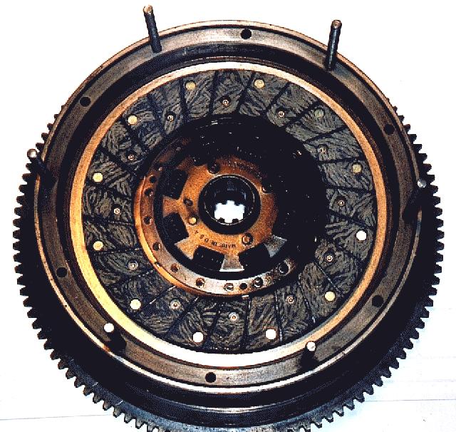
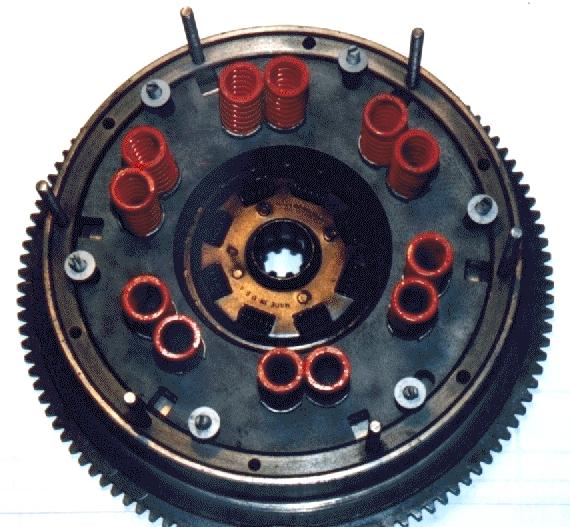
Description of Parts and Operation It will first be necessary to positively identify the different components making up the pressure plate unit in order to prevent any confusion further down the line so I'll deal with this unit only, as it's seen when off the flywheel, as I'm sure almost everyone can positively identify a clutch disc and flywheel, so, it's off to the classroom.
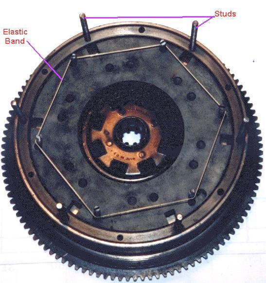
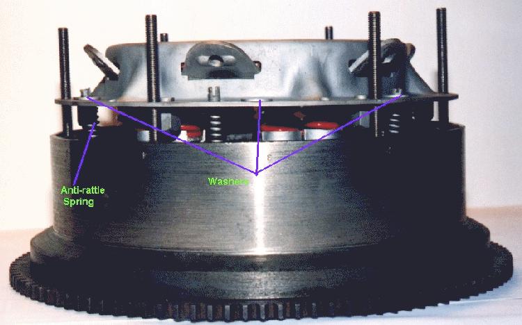
1) Looking from the outside or top of the pressure plate, which is the part you can see when it's bolted onto the flywheel, the strange shaped pressed steel outer housing with all the holes in it, and which also happens to hold everything else together is called the cover , it also has six drive blocks riveted to the bottom face which locate in corresponding notches in the circumference of the face-plate . 2) Mounted in the cover and able to pivot therein are six levers, which have the narrow end pointing inwards towards the centre for the throwout bearing to press against. 3) At the outer, or wider end of the six levers are six adjuster bolts and lock nuts for individually setting the height of each lever, all with their own anti-rattle springs , washers and pivot plates 4) A little difficult to see whilst the unit is assembled, but between the top of each lever and the cover is another conical shaped anti-rattle spring (kind of like a smaller version of the one behind the window riser escutcheon). 5) Spaced between each lever are two pressure springs making a total of twelve which provide the clamping pressure of the face plate. 6) If the pressure plate is now turned over, the thick, cast plate with the notches in its circumference, that presses on the clutch disc, is the face plate. The principal idea now, is that when the pressure plate unit is bolted down onto the flywheel, the cover compresses the twelve springs against the back of the face plate, causing it to sandwich the clutch disc (which is splined to the gearbox shaft) tightly between the face plate and the flywheel face. The unit as a whole will then turn as one, so providing the mechanical connection between the flywheel and gearbox shaft. Disconnection or release is achieved by the throwout bearing moving forwards, (when the clutch pedal is depressed) and pushing the inner ends of the levers towards the flywheel, causing them to pivot in the cover. This action then lifts the outer end of the lever upward against the adjuster bolt lock nuts causing the bolt to rise with it. The upward movement of the bolt in turn lifts the face plate against the spring pressure away from the clutch disc and flywheel. The gap created then allows the clutch disc to rotate freely or even become stationary in the small space between the face plate and flywheel which will then, in theory, allow any gear to be selected without causing any strange noises to be emitted by the gearbox internals (excluding the grinding noises caused by auto-trans drivers learning to double clutch). If you still don't really understand it's not the end of the world and it won't stop you from overhauling your unit. Dismantling the Unit Now for the exciting part where you get to rip the thing to pieces and I recommend the procedure be carried out working on a bench with the flywheel off the motor, (or spare flywheel) especially when it comes to assembly, otherwise you're going to have a terrible time battling against Isaac Newtons findings with the apple. First you'll need about 24 inches of 5/16" x 18 threaded bar (I believe it's called "All Thread" over there) cut into 6 studs 4 inches long, with 6 nuts to suit. 1) Screw a stud into every second mounting hole in the flywheel by locking 2 nuts together at the top of the stud, then tightening until the stud bottoms in the bolt hole. TAKE NOTE: Each stud must be screwed in completely and tightened into the bottom of the bolt hole in order to prevent it unscrewing itself when the nuts are removed during the dismantling procedure.
2) Mark the face plate in relation to the cover so that they can be re-assembled in the same relative positon in order to try and avoid any balance problems. 3) With a feeler gauge, check the clearance either side of the drive blocks and the face plate notches, and ensure the total does not exceed 0.015". If it does the cover or face plate will need to be replaced, so rather look for another unit now before you go any further. 4) Place the clutch disc in the flywheel with the raised boss upwards and the flatter side towards the flywheel, then slide the pressure plate down over the 6 studs.
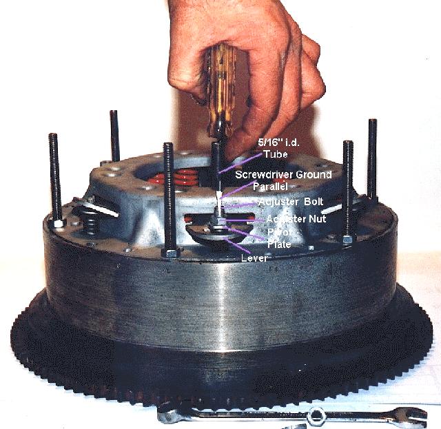
5) Screw the 6 nuts onto the studs then tighten them down evenly using a star type pattern until the cover is tight against the flywheel mounting face. 6) Grind the end of an old screwdriver to a parallel shape (see diagram) as opposed to a chisel like point, so that it will fit neatly right down into the bottom of the slots in the adjuster bolts,(a "T" handled driver works even better), then use it to knock back the lock collar on the top of the adjuster nut where it's been punched into the slot in the bolt. 7) A big help with this operation is to use a piece of 5/16" i.d. steel tube about 1 1/2" long which will fit snugly over the threads of the adjuster bolt. The screwdriver may then need to be ground a little on the sides so it can be slid down inside the tube and into the slot. This prevents the screwdriver from slipping out of the slot in the adjuster bolt, or the adjuster bolt becoming splayed whilst the nut is being removed.
8) Remove the 6 adjuster nuts from the bolts. You may need to turn them back and forth a few times initially to free them up, spray them with your favourite goose grease for a week, or, if they still won't move, scare the hell out of them with fire by warming them to almost cherry red with a gas torch. 9) Loosen the nuts on the studs in the flywheel by about 1 turn at a time in an even pattern and the cover will slowly rise with the levers, leaving the face plate, the 12 springs and the adjuster bolts with their anti-rattle springs and washers in the flywheel recess. 10) Lift the lever pivot plates off the top of the levers then lift the cover off the studs. TAKE NOTE: DO NOT LOOSE ANY OF THESE PIVOT PLATES AS THEY ARE IRREPLACEABLE.11) Lift the 12 compression springs off the face plate. 12) Remove the washers and anti-rattle springs from the adjuster bolts, then lift the face plate out of the flywheel and push all of the adjuster bolts out of the face plate towards the clutch face side. 13) With a screwdriver, gently pry the 12 spring seat cups off the back face of the pressure plate. Leave the fibre insulator washers inside the cups for the moment until you've got past the inspection stage. 14) Turn the cover upside down and remove the levers by pushing the outer end down against the conical anti-rattle springs and sliding them outwards, then unclip the conical springs from the cover. 15) Clean everything in your favourite goop and wire brush any rusty parts, preferably with a rotary wire brush on a bench grinder. (This is the perfect excuse to convince the wife, or girlfriend, that you'll be saving a fortune by buying that bench grinder you've always needed, and while you're about it what about the welding set and jig-saw, and woodworking bench and and and) A bonus would be to have everything glass bead blasted, but the down-side is letting those precious irreplaceable parts out of your sight for more than one minute as Murphy's Law states that,
to the ease with which said part can be replaced". Inspection and Repair Once everything has been thoroughly cleaned you can then inspect the following items for serviceability. 1) Check the working face of the face-plate, (that's the sort of smooth side) if you can see fine little hair line cracks in the working face that aren't very long and which radiate outwards from the centre, don't worry, they're not normally very deep and this is a normal characteristic of a cast-iron work face when it's been subjected to a fair bit of heat. Take it down to your local engineering shop and have them machine or grind the face, but emphasize that they must just true it up and it's not necessary to remove the cracks completely and possibly risk making the plate too thin. The Ford Model "B" literature recommends that you do not machine the plate to below a thickness of 0.530", and it should be flat and paralell within 0.001" after machining. However, if the plate has no cracks then I feel you can safely cut it down as far as 0.500" and compensate for the difference by adding shims of the corresponding amount to the isulator washers in the spring seat cups. Obviously if there are large cracks going right through the plate it'll have to be scrapped.
2) Check the face plate with a straight edge to ensure that it's neither concave nor convex, if so then see #1 above. If it seems flat (and you're on a tight budget) then it's OK and can just be cleaned up with about a 60 or 80 grit sand paper or emery tape. 3) Check the levers for wear and cracks, especially at the cover and adjuster bolt pivot points. Check for wear on the narrow ends where the throwout bearing contacts them. If they have slight flats on them from the throwout bearing, they can be dressed by grinding them on the side of a grindstone using an arc type motion to get the radius back onto the bearing contact area. If they have bad flats on them they will have to be re-built by welding and then ground back to shape. We use a normal arc welder with welding rods used for high carbon steels which the experts tell me are known as 29/9 rods (29% chrome and 9% nickel and the spec # is E312-16). If there are any cracks, and you don't have the know how or ability to repair them, you're going to have to get them welded up by a specialist, then you'll need to regrind to shape with a pencil grinder. 4) Check adjuster bolts and nuts for damaged threads or broken slotted ends. These bolts are also unavailable but can easily be machined up from a normal 5/16" x 24 high tensile steel bolt of the correct length, then slotted by hand with a hacksaw with 2 blades fitted to it. N.B. do not use mild steel bolts as they are not strong enough. If the bolts look OK and the threads are just burred a little, I'm sure your local machine shop could run a die-nut down them for you or you could dress them up with a thread file. If the nuts look like they're scrap, you're going to have to have some made up, or find the Model B part number for replacements. 5) Check free length of springs which should be around 2 1/4", but not be less than 2 1/8". All coils should also be evenly spaced If the spring has been too hot the coils on that end (face plate end) will have collapsed and be closer together than the coils on the opposite end and will definitely require replacing. Alternatively you could have an automotive shop with a valve spring tester check the springs for you. It should take around 100lbs at least, to compress the springs to 1 9/16".
Ford listed part # B-7562 as replacement springs for the "Model B" pressure plate which was a slightly stronger spring, 110lbs at 1 9/16", so as there is no known replacement as yet, yours can be replaced with this part # if they are unserviceable.
PLEASE NOTE: These are both emergency cures for units which should by rights be scrapped but cannot be due to lack of a replacement, or funds).9) If the fancy takes you, you can now paint the cover and all the springs your favourite shade/s of aerosol. Do not paint the face plate (no one will see it anyway) or every time you make the clutch work a little hard to get out of that driveway or hold the car at the traffic light for a few more seconds, you'll be wondering where that burning paint smell comes from and why smoke keeps wisping out of your bell-housing and up through your floor boards. Assembly and Adjustment Now for the big moment, you should now have 1 face-plate, 1 cover, and a host of other spares all in multiples of six, including the pressure plate springs and cups (2X6), so let's "have at it". 1) Place the clutch plate back in the flywheel with the flat side down
and the spring boss up.
3) Slide the straight anti-rattle springs over the adjuster bolts and then slide the flat washers down on top of them. 4) Fit the twelve spring seat cups into their locating holes in the back of the face plate, then, if you removed them, place the insulator discs (or washers) in the cups, including any extra's you may need to compensate for material removed from the face plate, and stand the twelve springs in the cups.
5) With the cover upside down, clip the big side of the six conical anti-rattle springs into their respective positions in line with the lever slots in the cover. 6) From outside the cover, with the indents on the lever for the pivot washers facing down, slide each of the six levers through its slot in the cover, over the small end of the conical spring, until the slots in the lever can locate in the pivot slot in the cover.
7) Flip the cover over and slide it down the studs screwed into the flywheel. You will now have to jiggle the face plate in the flywheel, remembering to keep it central, until the adjuster bolts line up with the holes in the levers.
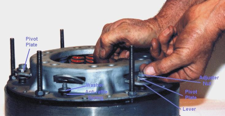
8) Screw the 6 nuts onto the studs and slowly tighten them down evenly, once again using a star type pattern. At the same time make sure that the adjuster bolt ends enter the holes in the levers, and the locator blocks on the cover line up with the notches in the face-plate. This is probably the most difficult part of the process, so have a little patience as it may be necessary to loosen the cover off a few times to get the face plate aligned correctly. 9) Screw in and tighten six pressure plate bolts into the remaining holes in the flywheel to pull down the cover completely. 10) Slide the six pivot plates, (with the two little legs pointing downwards) onto the adjuster bolts and ensure the legs locate in the dimples in the levers. 11) Screw the six adjuster nuts onto the adjuster bolts by lifting up the inner end of the lever against the conical springs in order to get the bolt to stick through.
12) With your piece of 5/16" i.d. tube slid over one of the adjuster bolts, and the screwdriver in the slot, adjust the nut until you get a distance of 11/16", measured from the top face of the rear of the lever, down onto the cover.
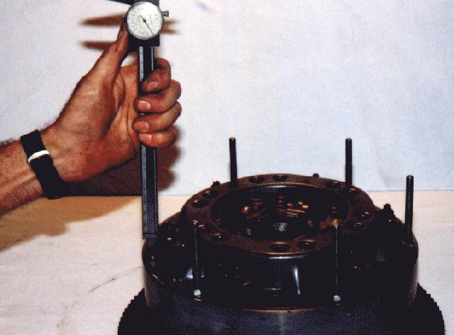
13) The lever should now be just above the horizontal plane in relation to the flywheel face, so now take a measurement from the throwout contact point of the lever down onto the clutch plate, and set the rest of the levers to this same height.
14) Once you're happy that all the levers are adjusted evenly, knock the collars of the adjuster nuts into the slots on the bolts to prevent them from turning. 15) Remove the six bolts and six nuts holding the pressure plate to the flywheel, then remove the six studs from the flywheel. 16) You now have a fully reconditioned and adjusted pressure plate ready to put into action in your pride and joy.
Updated 10:03am Sunday, Dec. 6th, 1998 This page has [an error occurred while processing this directive] since Aug. 26th, 2001.
|